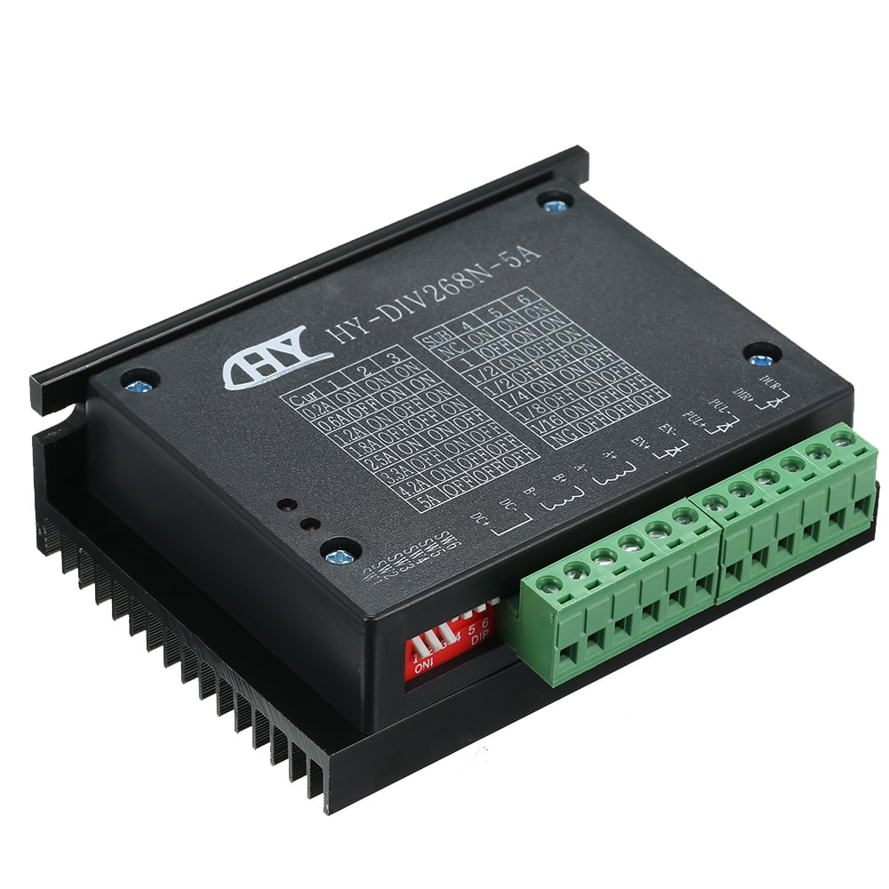
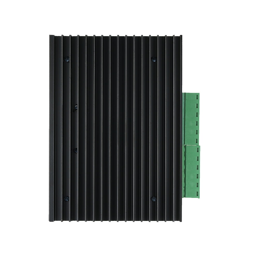
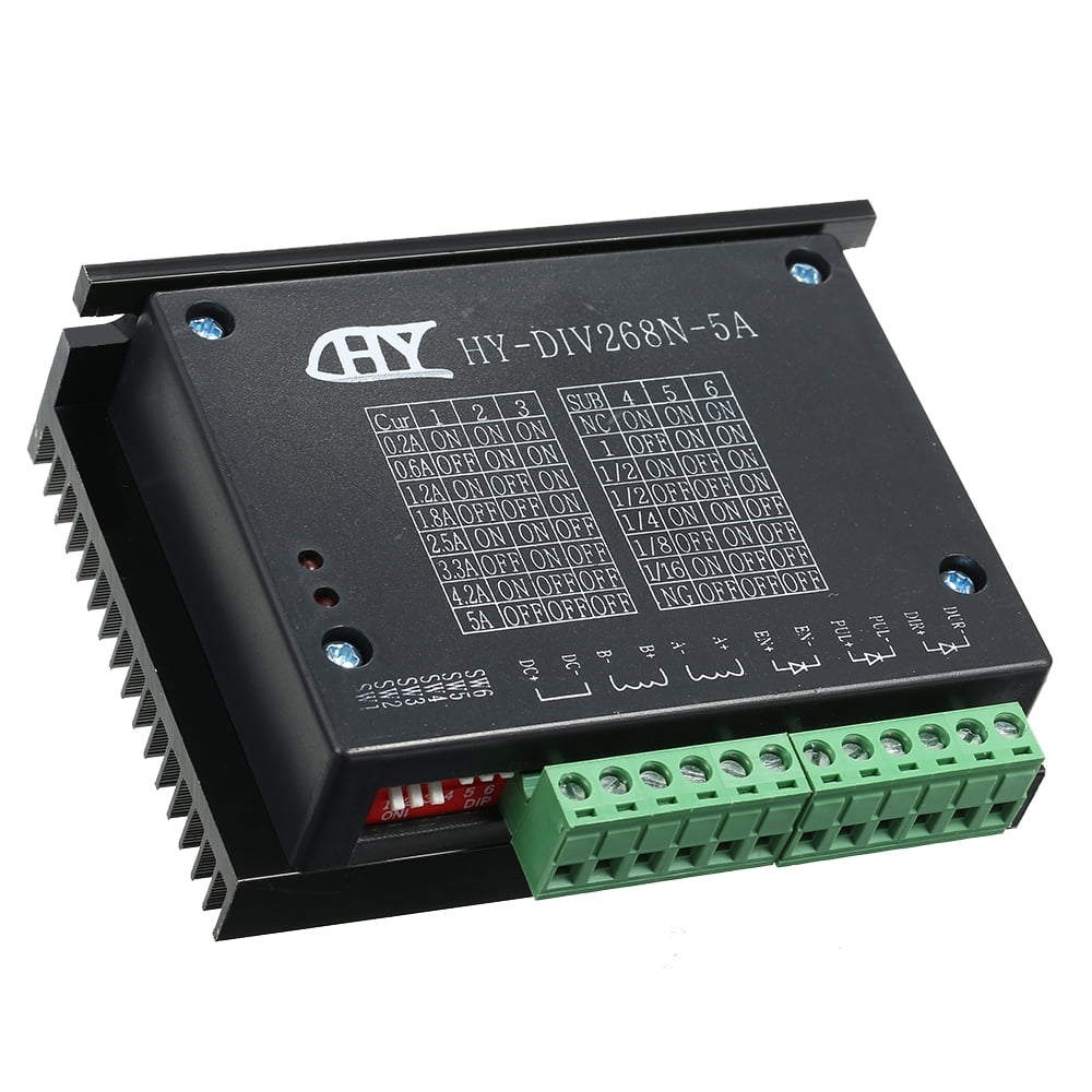
HY-DIV268N-5A Subdivision-Type Two-Phase Stepping Motor Drive DC 12 ~ 48V power supply
$11.39
500 in stock
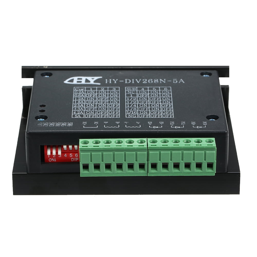
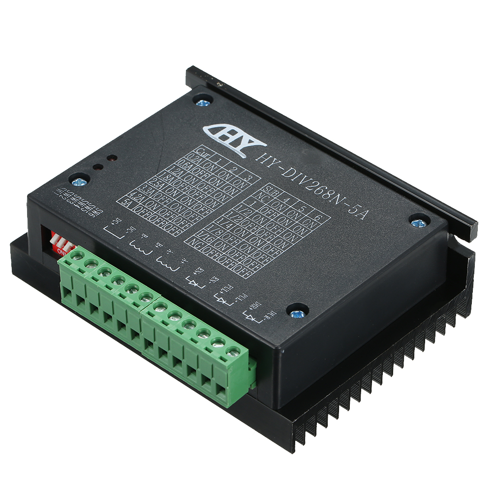
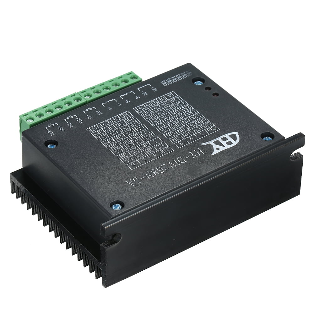
Two-phase stepping motor dynamic voltage 12 to 48V, the current is less than 5A outer diameter of 35 to 86 mm. This drive using the drive’s current loop subdivision control, the motor torque ripple is very small, low-speed running is very smooth, almost no vibration and noise. High-speed torque is much higher than other two-phase drive, high positioning accuracy. Widely used in the engraving machine, CNC machine tools, packaging machinery and other high resolution requirements on the device.
Features:
Average current control, two-phase sinusoidal current drive output.
DC 12 ~ 48V power supply, the internal integration of 12V and 5V .
Optically isolated signal input / output.
Overvoltage, undervoltage, overcurrent, and white short-circuit protection.
Widely used in the engraving machine, CNC machine tools, packaging machinery and other high resolution requirements on the device.
Specification:
Input Voltage: DC 12 ~ 48V input
Input Current: 1 to 5 amps, select the drive a stepper motor.
Output Current: 0.2A ~ 5A
Temperature Operating Temperature: -10 to 45 ?
Storage temperature: -40 ? to 70 ?
Material: ABS & Metal
Item size: 10.4 * 8.6 * 3.3cm / 4.09 * 3.39 * 1.3in(L * W * H)
Item weight: Approx. 218g / 7.69oz
Package size: 11.9 * 9 * 3.9cm / 4.69 * 3.54 * 1.54in(L * W * H)
Package weight: 243g / 8.57oz
Package list:
1 * Stepping Motor Drive
Instruction:
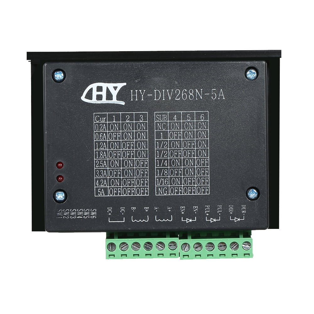
Control signal interface
– Figure 1 is a wiring schematic of the drive
– 1, the definition of control signals
PUL +: step pulse signal is input side or the positive pulse signal input positive terminal
PUL-: the negative input of the negative input pulse signal or a positive pulse signal
DIR +: stepping direction signal input to the positive terminal or negative pulse signal input to the positive terminal
DIR -: stepping direction signal input of the negative side or reverse step pulse signal input negative terminal
EN +: offline can reset signal input side is
EN-: offline can reset signal input negative terminal
Offline enable signal is active, reset drive failure to prohibit any pulse, the output of the drive
Power component is turned off, the motor holding torque.
– Control signal connections
– PC control signal can be high, also can be low effective. When active high, the control signal
– The negative side together as a signal to active low, positive side of all control signals together as a signal common.
– For example, open-collector and PNP output interface circuit diagram is as follows:
Figure 2. Input interface circuit (common cathode connection)
– Note: the VCC is 5V, R short?
– VCC value of 12V, R 1K, more than 1/8W resistor;
– VCC value of 24V, R 2K, more than 1/8W resistor;
Function selection (DIP switch on the drive panel)
– Set the motor per revolution
The drive to set the number of per motor revolution is 200 (whole step), 400 (2 segments), 1600 (8 segments), 3200 (16 segments).
The user can drive the front panel DIP switch SW3 is SW4 bit of the drive to set the number of (such as Table 1??
Table 1
– Set the output phase current
– To drive torque stepper motor, the user can drive panel DIP switch
– SW1, SW2 is to set the drive output phase current (RMS) unit amperes, the switch position
– Corresponding to the output current, output current value corresponding different types of drive. Concrete are shown in Table 2.
– Output Current (A
Table 2
Current setting
– the semi- functionality
– The semi- function is a step pulse 200ms, the driver output current is automatically reduced to the rated output curren
- Average current control, two-phase sinusoidal current drive output.
- DC 12 ~ 48V power supply, the internal integration of 12V and 5V .
- Optically isolated signal input / output.
- Overvoltage, undervoltage, overcurrent, and white short-circuit protection.
- Widely used in the engraving machine, CNC machine tools, packaging machinery and other high resolution requirements on the device.
| Dimensions | 4.69 × 3.54 × 1.54 in |
|---|
Only logged in customers who have purchased this product may leave a review.
Related products
Electric Motors
TitanPro TOC5 HVAC Oval Motor Run Capacitor. 5 MFD/UF 370 Volts
Electric Motors

Reviews
There are no reviews yet.